|
|
|
Having shoveled heaps of Internet information on the tornado and tornado
technologies provided by different authors (and believe me, there were quite a
lot of them), I feel sort of making a conclusion. At first sight, it may seem
rather pessimistic. Finished devices with clear operating principles or at least
ones functioning in reality, apparently, do not exist. Just look, is it possible
to keep in secret the design of any device of superior capabilities at our time
of fully open information? If something like that were really invented, the
smallest details of the design would spread around the world at a break-neck
speed no matter what efforts might have been made to conceal the fact of the
invention. So a particular device is not likely to have ever existed before or
be available now regardless of optimistic reports of individual authors.
However, all the above does not mean that the search should be terminated. And I
do not want to say that in the search of perpetual motion only the search itself
is perpetual
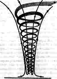
Thus we are facing “nothing but a modest” task: to engineer a tornado. The first technical implementation that immediately comes to mind is the Ranque vortex tube. This, in my opinion, is an excellent attempt to implement principles of a natural phenomenon in a small cylinder. The theory of this tube is poorly substantiated. For more than 70 years all attempts to reach a single agreement on causes that make the incoming flow split into the hot and the cool flows have failed. And there is more to it than that! Another most important “strangeness” (mentioned very seldom) incomprehensible at first sight is that the cool and the hot flows in the Ranque tube rotate in the opposite directions! The internal cool flow is faster and can rotate at nearly several million rotations per minute (!) but in the direction strictly opposite to the external flow. I would like to catch on this to put forward my own theory of the Ranque-Hilsch tube and hence the theory of the tornado itself. The postulate is as easy as a pie. External and internal air layers moving forward in the tube respective each other (remember, hot air in one direction and cool air in the opposite one) will invariably begin to whirl about due to mutual friction. As a result, these vortices will twist into a whirling spiral by which the external and the internal cylinders of the whirling air will be separated. The cross section of the tube will look like the following: Two cylinders rotating at a breakneck speed in opposite directions form a boundary layer in between. On the tube cross section it looks like a real ball-bearing with quickly rotating balls that do not change their positions. I think it is a logically safe graphical explanation of the “odd” reverse rotation of the external and the internal flows inside the tube. Nobody can look into the functioning tube, but all these balls and rolls are likely to be the essential part of the tube giving rise to many of its odd phenomena. Meanwhile, something very likely (if not exactly the same) is contained in Schauberger’s works:
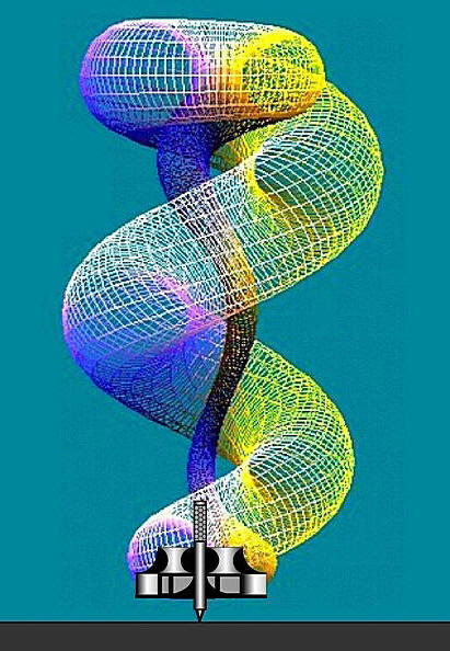
I believe this is actually the CROSS SECTION OF A TORNADO!
Based on this model I am going to build my own model of a tornado. Hello, is
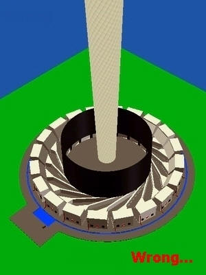
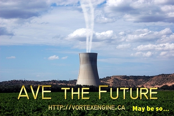
there anybody to hear? So, we are going to have a tornado. But first, a couple of words about “wrong” models. All of them are more or less similar.
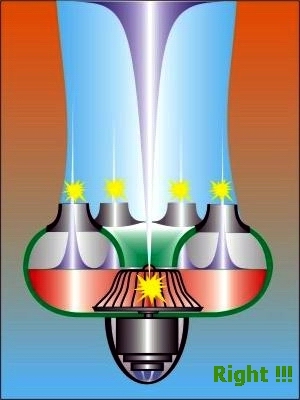
A vivid example (the left and the central pictures) of such a model is the one built by Louis Michaud (Canada). This model totally ignores the real structure of a tornado (and therefore no worthy result was obtained using it despite huge efforts, money and time!). I, however, enjoyed the second picture (in the center) though, probably, not in the sense implied by the author. In my opinion, the right-hand picture shows a more successful implementation: In a well-developed tornado there is ALWAYS a considerable flow directed from the CENTER DOWNWARD with the structure and properties similar to an ordinary water funnel in a bath tub sink. This funnel is just the “mobilizing and shaping” structure to attract matter (and energy!) from all sides surrounding the funnel. In natural conditions the surrounding air would tend to move with all its mass from the periphery to the central vertical vacuum column to form a grand picture of a developed tornado! To the right is just what Schauberger used to call a VORTEX TROUTE (vortex throat).
Such is indeed the thing I tried to reproduce in a “more correct” (from my
point of view) picture on the right (in contrast to the two previous ones)
Firstly, an incredibly blue sky very high above. Secondly, a black-gray “solid” rotating cylinder with lightning flashes at the sides. I would venture a remark: a tornado is not just whirling air columns. It is, in fact, two huge air cylinders inserted into one another and rotating with different velocities (2-fold difference) in one direction. Moreover, the outside tornado cylinder is represented by spiral rolls (please forgive me for this incorrect comparison) of the boundary layer bundles. Such “ball-bearing rolls” are rotating at a relatively low speed, while in the internal area there are rotating air masses similar to a funnel outgoing from a bathtub. And while watching a tornado we actually see an interim layer brought about by the rotating air cylinders inserted into each other! (let me repeat, with the two-fold difference in the rotation velocities). There are lots of such pictures on Internet sites, just look, for instance, at the ones below:
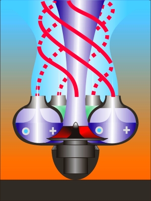
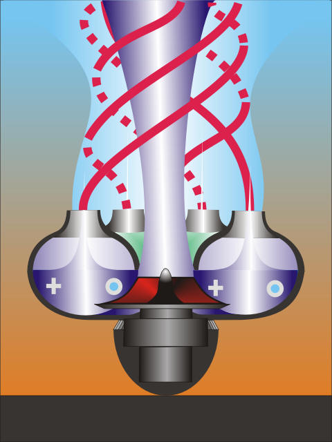
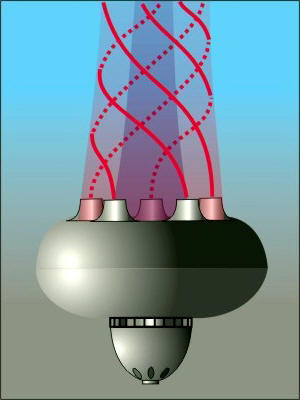
Now it is high time to propose a design of a tornado generator based on the
above principle. The unit is ABC simple. We may arbitrarily call it a “tornado
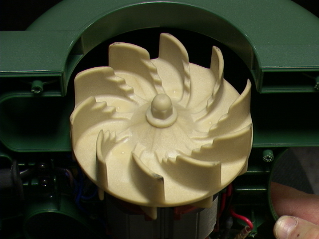
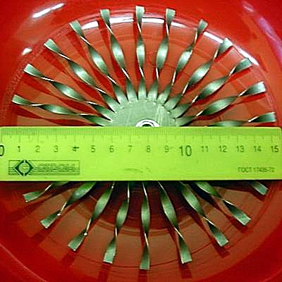
brewing pot”. The simplicity of the design is really striking. It can be made of two small washbowls (acting as dielectrics), the upper bowl having a hole with a flared metal part inserted into it. Thus we have a high-velocity electrical motor with a centrifugal turbine sort of a car turbocharger type. For example, one of such turbines 10-20 cm in the diameter is capable of rotation at 180 K rpm!!!
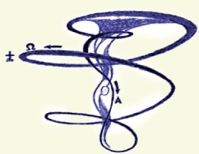
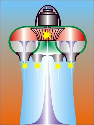
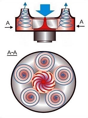
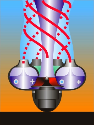
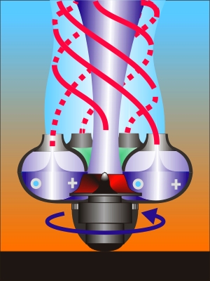
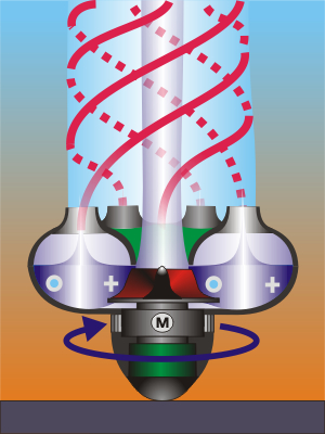
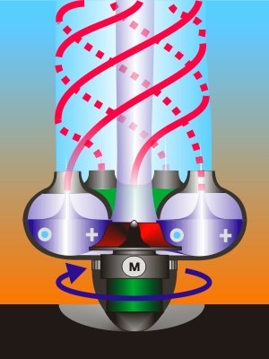
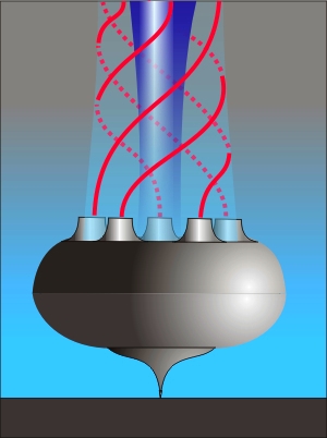
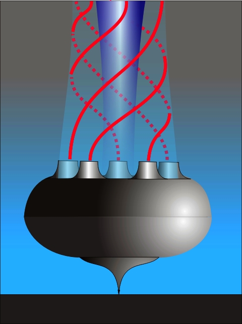
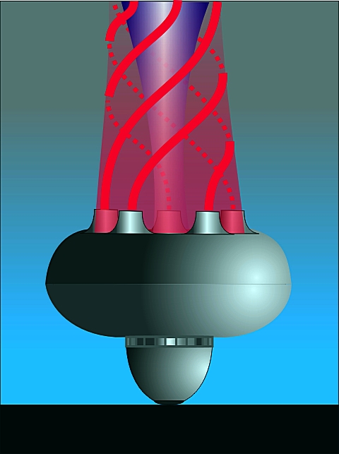
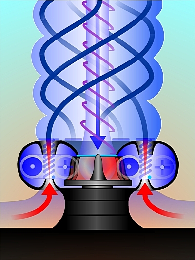
However, I do not think we will ever need such a velocity. I suggest being limited by “Schauberger’s parameters”, i.e. a 15-20 cm turbine rotating at 15-20 K rpm, with the external diameter of the whole structure being 50-100 cm. The rpm velocity is high but quite realistic. Let us start rotating it very slowly. At a low rotation speed an internal self-eversible torus is developed whose movement I tried to explain repeatedly on pages of this website. The figure (or the body, to be more exact) is remarkable in itself and, in my opinion, “prone to” self-acceleration. As the rotation velocity increases, the flow gives up looping and the Coanda’s effect displays itself in all its beauty. May I remind you that it means a jet flow of liquid or gas getting attached to a nearby surface. This is why air begins to attach itself to the “throat” as it moves outside. But Nature hates emptiness, and soon outside air starts to be sucked in through the center to make up for the air that escaped from “the pot”. Two counterflows are developed – one incoming in the center and the other outgoing at the periphery. And the two flows are not mutually friendly; they rub against one another producing multiple whirls. It comes about like this: As the velocity increases still more, the whirls acquire a specific shape and are transformed into the “air rolls” that I depicted at the beginning of this page. In the long run everything is converted into something similar to what I depicted, and I think this is a jump-like (!) process, as shown below:
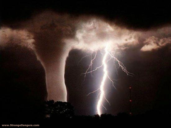
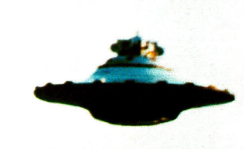
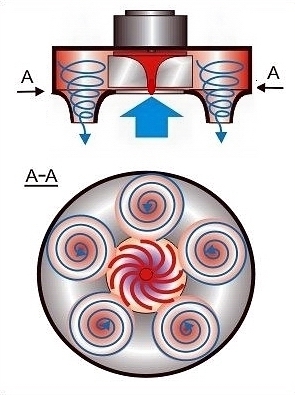
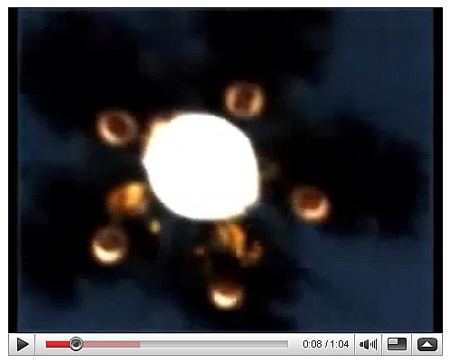
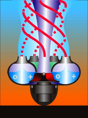
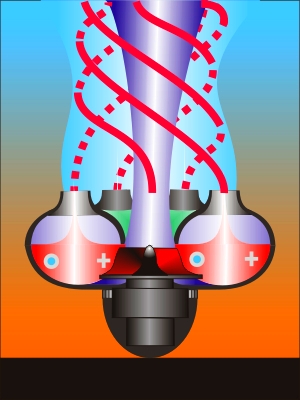
The incoming (sucked in) air in the center, rotating spiral rolls of the air flow (red), the outgoing air at the periphery (blue). Now please refer to the animated picture of the cross-section A-A below: A real tornado may have a similar cross section. Moreover, it is at the same time an electrostatic generator with the rotation center as the “minus” and the periphery as the “plus”. Reaching the breakdown voltage results in lightning strikes that have an additional “turning effect” on the rolls (see the operating principles of a PFT motor described in detail at Naudin’s site). Probably, these are the lightnings described by casual observers who chanced to look into the tornado’s trunk from below. Incidentally, the same is mentioned by pilots of aircraft who happened to fly over the tornado’s “eye” from above. The fact that a tornado is an electrical machine is confirmed by the picture below:
I believe the mutual electrical attachment of the peripheral “plus” and the central “minus” is the main reason for the tornado trunk’s stability. And it is quite likely V. Atsyukovsky’s model of the tornado structure which, in principle (!), contradicts to all generally accepted models is true. The essence of the model is very simple: There is a powerful downward flow in the center of a well-developed tornado (exactly like the funnel in a bathtub). The end of the flow impacts the earth followed by an implosive emission of energy. The flow slews upward (with a mandatory “surf” at the tornado’s foot). The twisted air masses move upwards in a rope-like flow Watching a tornado we see only a thin-walled cylinder of the boundary layer! In motion this boundary layer gets as strong as armor. The external atmospheric pressure compresses the “dynamic cylinder” and narrows the rotation radius of air masses making them rotate faster. There is heat and electricity exchange between the huge vertically extended “dynamic cylinder” and the environment. Given below is a structure of a typical tornado in interpretation of L. Fominsky:
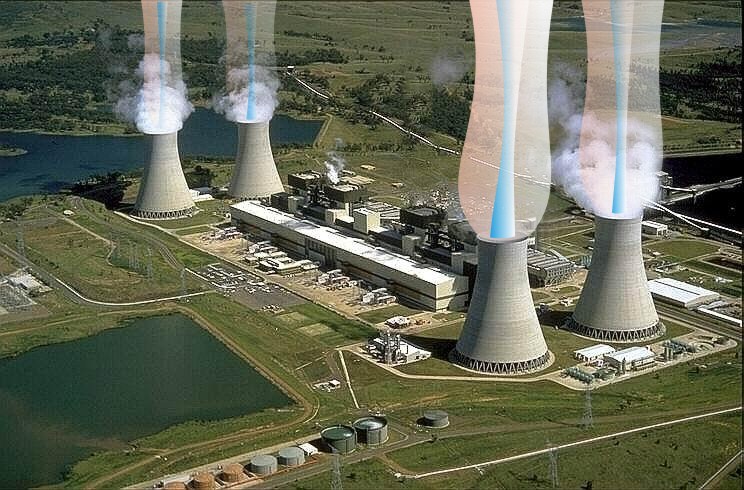
In seems to me that we can finally come to a stationary power generating system with direct energy pick-up between the grounded motor and the flared metal throat (the unit actually consuming only air and water!)
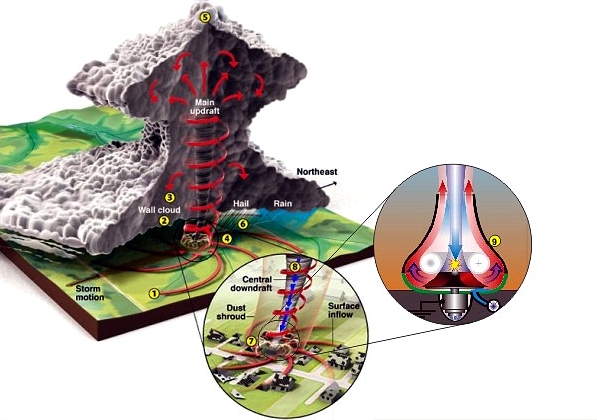
The above can be understood as a huge vertical air shaft for rotation of a giant vortex! Or: A looped air toroid (tornado), actually a huge open Ranque tube. The conversion of thermal energy of the environment into mechanical and, finally, electrical energy is quite a worthy weapon in fighting the global warming! Anatomy of a Tornado
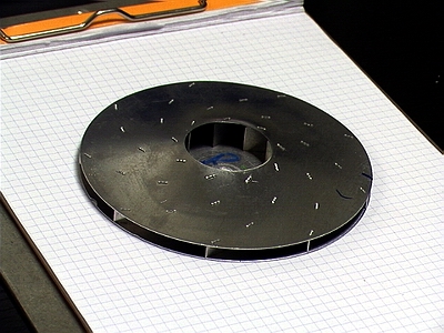
1. Warm, moist air at the surface rises rapidly, creating an updraft. 2. Falling rain evaporates, cooling the air around it. 3. The wall cloud rotates as it's hit with winds from opposite directions. 4. As the rotation intensifies, a visible funnel drops out of the clouds. 5. A prominent overshooting top forms when the updraft is very strong. 6. Powerful updrafts give hail time to form. 7. A dust shroud is kicked up by the tornado's strong winds at ground level. 8. Central downdrafts appear in some tornadoes. 9. Tornadoes generator. I am expecting a question: why are there only 5 balls in my “ball bearing”? The answer exposes in full glory the theory of Valery Shikhirin whose findings are accessible from the same site with adjacent buttons. He associates them with the number of rolls in a tornado. Indeed, make use of the following link to see pictures of a most powerful typhoon “Isabel” taken from space in the period of its maximum activity (incidentally, typhoons “Ivan”, “Katerina” and others have the same structure). http://www.enterprisemission.com/hurricane3.htm (Only the link is published here not to infringe the copyright)At that site the so called “Tornado’s Devil Star” is described. Moreover, no less intriguing information has appeared in the Internet of late! A number of experiments with the “Newton’s bucket” (Aren’t all these names remarkable!) were conducted in Professor Bohr’s laboratory in Denmark. Let me remind you that the Newton’s bucket in such experiments is a usual cylindrical vessel (30 cm in diameter and of the same height) filled with water the bottom of which is rotated by a motor (i.e. there is a flat round organic glass disk attached to the bottom). So, the lab experiments show that during rotation the bottom of the vessel is capable of self-organization and acquires the appearance of absolutely well-defined geometrical figures from a triangle to a hexagon, according to Danish researchers. And one of the most stable figures turned out to be a pentagon! This is the central photograph of the tests (top view), which is actually the process I would like to repeat either with water or with air. In the center we see the organic glass bottom of the vessel rotating at about 300 rpm. The cycling water follows the trajectory of a rotating self-eversible torus I am constantly speaking about wherever I can. The “star” in the center of the vortex is absolutely still at a certain bottom rotation velocity. From the videoroll of that site one can clearly see the flows circulating in the following way:
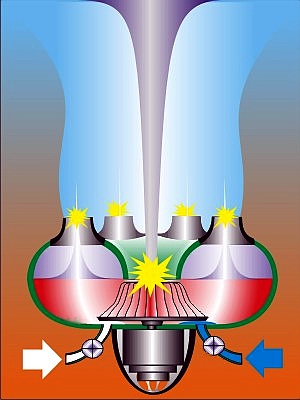
Still more intriguing are drawings made by witnesses of a tornado that occurred in the city of Ivanovo in 1984. One of them is a “print” of the tornado effect manifested by a felled forest when a twister suddenly descended from a thunderstorm cloud to the earth’s surface and “made a little stop” before moving further crashing everything on its way. Just because of this my animated picture above (see the A-A cross-section, the flow from the “tornado pot”) has 5 “ball-bearing” rolls. Moreover, taking into account the results of the Danish experiment, the final design of the optimized “tornado pot” is transformed into something I tried to depict below (the “pot’s” cross-section + the removed upper part). Try to look at the flows as at a three-dimensional image! Aren’t we going to have a sufficiently logical and well-balanced picture? The area of the central input orifice is equal to the area of the 5 output nozzles.
Frankly speaking, I have spent too much of the site’s space trying to express my ideas. However, the design principles I am promoting are not as simple as they might seem at first glance. If I begin just to describe what, in my opinion, goes on inside this structure, then the site will expand multifold and the essence will be lost in the ocean of words. Therefore, I am just going to mention effects and fields of physics that I believe are present here. mechanics, centrifugal forces (elements of the curvilinear movement theory, gyroscopes); electricity and magnetism (electrostatics, balloelectricity, centrifugal charge separation, the magnetic field of rotating charged particles, the ESD theory, MHD generators, Lorenz forces); aero-hydrodynamics including Bernoulli’s, Coanda’s, Magnus’s law effects; thermal capacity, heat exchange (just think of unusual water properties!); exotic phenomena like the PFT motor operation, transformation of the boundary layer into an ascending spiral, acceleration of axial vortex motion by the Browning motion ordering (!); Ranque-Hilsch.A detailed investigation into the above issues and phenomena is a task for hundreds of research laboratories for decades to come. Therefore I suggest the easiest way out – modeling. Here so far the focus has been made on the description of an alternative energy source. It is easy to understand that simply by turning such unit upside down we may obtain an alternative flying vehicle. Such as the below “lampshade” with one big central “nozzle” and 5 small peripheral “nozzles”.
Many readers might think I am repeating myself. Indeed, some of my colleagues made individual attempts to manufacture, at my suggestion, similar devices. Look at the picture of one of such units. After the startup of the electrical motor (running at 10 K rpm and having a small turbine on the 70 mm shaft) a seemingly paradoxical thing occurred: the device got sucked (and very firmly at that!) to the floor.
Does it mean the attempt to make a gas toroid has failed? Alas, what I
suggested was not correctly understood (I don’t want anybody to take
offence!). By centrifugal forces the air was simply swept away from under the
“potential flying saucer” and the device was pressed to the floor by atmospheric
pressure. Though, perhaps, a pretty good device for walking on the ceiling might
have been obtained. However, our final goal is different: to obtain a universal alternative flying vehicle by harnessing the tornado and making it tame. Therefore, we are going to update the design fundamentally taking into account the negative experience.
The name a “flying lampshade” will, probably, fit best of all. A
similar one hangs before my eyes in my bedroom.
But to be more precise, this is actually an open-type Ranque tube. Its resemblance to Schauberger’s “Repulsin” is also obvious. My opponents will immediately have a question: where does the lift come from if the central incoming flow is equal to the peripheral outgoing flow and hence the resultant impulse will be zero?
Not entirely so… To be more exact, it is entirely different.
Non-compensated centripetal forces appear as the air flows around the
lower part of the dome. These are the very forces that press a pilot into an
aircraft’s seat when he loops the loop. In this very manner an aircraft
decelerates by reversal of the engine or with the drag parachute during landing.
Based on this very principle a Pelton bucket turbine works in hydropower
engineering. To add all the effects I tried to describe earlier for the
“power system”, what a splendid apparatus could be fabricated for the needs of
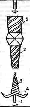
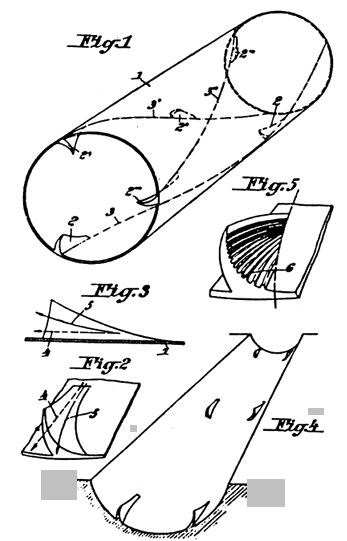
the Emergency Ministry! A few words about the design details: Dimensions: Many people believe that dimensions of a soliton (an aerial toroid) are discrete and have specific relations between the outer diameter and the inner diameter (the “eye” diameter). On my own behalf, I would add that the number of bundles-vortices that make such a toroid is also discrete. In the example based on the Danish experiments I suggest a 5-roll design with the outer diameter of about 60cm (according to Alexander Makhov, one of the discrete torus sizes close to this figure is almost exactly 70 cm), the “eye” diameter in this case is about 10 cm. Materials: I suggest using epoxy to make a light-weight and durable package. The flares of the incoming and outgoing flows should conduct current in which case we may hopefully obtain a high-voltage potential! Working medium: It may be water, air. In this situation the working medium volume is greater than the dimensions of the device itself. The device, one could say, is open-type with intensive energy exchange with the environment. Turbine: It is one of the most interesting issues. In my proposals I completely ignore Viktor Schauberger’s wave turbine, pipe turbine, “horny” turbine. I simply regard all the above as absolutely useless technologically superfluous things. However, I do not want to ignore the working medium trajectories that Viktor Schauberger (together with Professor Poppel, his follower from Stuttgart) tried to obtain. I mean the sophisticated curve below:
What I do disregard are sophisticated methods of obtaining such trajectories… Probably, the most successful version is the turbine of a usual car turbocharger capable of producing something alike.
Or even the one like this, homemade (!!!) And even such a “star turbine” (literally, the top of manufacturability and operation reliability!). Moreover, providing a capability to enable the Magnus effect: What I mean is: the design of the turbine is not the main thing! It is the working medium trajectory that really matters! The principal task is to generate the below air toroid based on one of our available designs (the picture is provided by the courtesy of Gaby Muller and taken from her site.
The Motor I believe a very powerful motor is not needed; rather it should have a high rotation velocity (just like it was in Schauberger’s design). When the air toroid rotation is looped the flows become “odd” such that they have higher angular and rotation velocities and enable self-acceleration of the design when flowing to the center. I draw you attention to the table below that lists motors used mainly in aircraft modeling. However, even an electrical saw motor might come in handy.
And this “photodocument” is sort of a joke (from a series of well-known photos by Billy Meyer). The joke, though, is very true to life (below is not just a picture – push to see the VIDEO)...
By the way, has anybody made any of Schauberger’s ideas work? H’m, …. Look at a similar option like this:
Do you say it’s simple? It depends…. Does anyone want to try? I suppose it might work and be quite interesting at that… AN ALTERNATIVE FLYING VEHICLE
And I would call this design (top of simplicity and engineering skill!) the
PANDORRA’S
BOX.
Please pay attention to the perfectly matched rotations of the working medium flows: The outer size of 30-60 cm in diameter seems to be just the thing … A car compressor turbine plus a 20-30K rpm motor (perhaps a high-velocity motor from a construction tool). And finally, a “VIDEOFILE OF A FLIGHT” (push the picture below). Fundamentally, this video is a skilful provocation and forgery, but look how strikingly identical is the thinking mechanism of the majority of people!
It is not unlikely they are also familiar with this website:
The pseudo-UFO joke is worth laughing at, however … the device itself proved to be quite real and operable! It should be only noted that the designers of this model have paid too much attention to appearances and completely misunderstood the main idea of the design! And this idea (in my opinion) has not been disclosed. Just like in all Hutton’s models. Further I would like to present my own vision of the design and explain its principles: A Tornado Generator
I am not going to repeat myself and assure you that making a tornado is an easy matter. Nevertheless I suggest trying to fabricate it by a method that actually ignores all known methods used by other researchers and focuses on the following items:
1. An air whirl/twister/tornado can be observed in nature in a wide range of
sizes – from several dozens centimeters to several kilometers. Let’s try to
engineer the smallest one and then we will see!
2. The device shell is a rigid composer of the most loaded and critical part of a tornado - its base (the foot). 3. The device turbine is a normal centrifugal type and has 3 functions: The process startup (ramping up to the operating mode) Pick up of excessive energy Brake (if needed) 4. The vertical water-aerial column with the central TOP-DOWN VACUUM FUNNEL (theoretically unlimited in size) is the surface of a huge heat exchanger sucking thermal energy from the environment and simultaneously an acceleration trajectory of the vortex working medium. 5. The umbilical tubes for air and water below are additional process controllers. 6. Ramping up to the operation mode is sure to go in a jump-like manner! Perhaps, this indeed happened in one of the experiments carried out by Viktor Schauberger’s followers (when one of the models was swept away from the pedestal and hangar roof was pierced through). In this case an additional and more powerful BRAKE is likely needed!
Somebody will ask: you really say all the above is difficult for
implementation? OK, let’ put it in a simpler way: PANDORRA'S BOX-2 Specifically, there are 6 funnels here (the main one is virtual going from the center downward, and the remaining five funnels are funnel-like shapers of the boundary layer of the tornado placed at the periphery and directed upward). The resultant dynamic structure is just a “civilized tornado”, the “tamed vortex” that can be controlled in order to structure and pick up energy scattered in space. I would not say that everything is in strict conformity with Viktor Schauberger’s ideas. Perhaps, even contrary to them … From his heritage I am taking what I think to be the main idea: any twisted funnel is completed with an implosive burst! Probably, the main idea of all known Viktor Schauberger’s patents is contained in the schematic drawing below:
I venture to express orally a “primitive thought”:
Nobody would ever give the name of the perpetual motion machine to a wind mill that makes use of usual horizontal wind for hundreds of years. I suggest a similar idea – to use the energy of a tornado, i.e. the energy of “twisted vertical wind” (push the picture below!):
What is left to do is “a mere trifle” – we have to put one of the devices suggested here into the basis of such vortex, eliminate the chaotic behavior and unpredictability and begin to control the thing earlier referred to as “a mere accident”! I wish everyone would watch all movies placed at youtube.com by tornado, vortex, dust devil queries. Look attentively at the videofiles and you will understand that everything works based on the principles I tried to explain here. A small comment. All the videofiles of artificial tornadoes look quite impressive. But for me they are not … too convincing! I am impressed only by videos of natural tornadoes and whirlwinds. Because in all of them there is always: A CENTRAL DOWNGOING VACUUM BUNDLE AROUND WHICH EVERYTHING IS FORMED (THE SO CALLED “VORTEX THROAT”) Those who will be the first to understand it will receive a KEY TO CONTROL a stable TORNADO.
Best regurds Evgeniy Aseev
|
|
© 2015 Freely quoted with reference to the website of the author Свободноцитируемый, со ссылкой на веб-сайт автора
|
 ! There is, indeed, an
example of successful implementation of a super design, but the inventor is
Nature and its invention is a tornado. Plain as it may seem at first sight,
it is at the same time a most complicated phenomenon. A destructively powerful
and extremely vivid outburst of natural energy with a detestable theory of its
origination and a recurrently used phrase like “this needs further research”.
Still, I suggest trying to reproduce something similar! But before doing it we
ought to have some knowledge (or at least our own wrong beliefs)
! There is, indeed, an
example of successful implementation of a super design, but the inventor is
Nature and its invention is a tornado. Plain as it may seem at first sight,
it is at the same time a most complicated phenomenon. A destructively powerful
and extremely vivid outburst of natural energy with a detestable theory of its
origination and a recurrently used phrase like “this needs further research”.
Still, I suggest trying to reproduce something similar! But before doing it we
ought to have some knowledge (or at least our own wrong beliefs)
 of principles that
lay “inside”.
of principles that
lay “inside”.


 . As a rule, nobody
sees the funnel in the tornado displayed here since it is hidden by rather
opaque masses of a boundary layer. This funnel may be seen only in photographs
and video movies of the most “transparent” tornadoes (shown many times on many
pages of the website)
. As a rule, nobody
sees the funnel in the tornado displayed here since it is hidden by rather
opaque masses of a boundary layer. This funnel may be seen only in photographs
and video movies of the most “transparent” tornadoes (shown many times on many
pages of the website)