|
|
|
The author of the article gives a brief description of the real
design of aircraft engine. Probably, this design is not similar
to Schauberger's one. However the very appearance of some ideas
is rather interesting. Different people in different places and
time come to the same conclusions. Whether people think in a
common way, or Nature laws are the same. Could you believe that
the author of the article has never read or heard about
Schauberger's works (I mean his engine, which operates on
environment energy and has levitation properties)? But by
accident (thanks to Internet) when come upon the description of
designs, I was surprised to find so much in common between
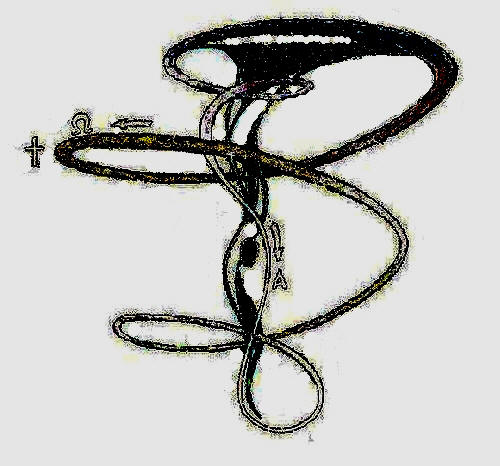
Shauberger's ideas and my suppositions. Outwardly Schauberger's
engine looks like the following (see Fig.l):
Fig.1
The possible internal device is shown in Fig,2 (the device is
turned upside-down with respect to the photos).
Fig.2
Since the author of this work does not purpose to appropriate
other's fame, then there is an attempt to explain easily the
arrangement of the engine. Besides, in spite of the fact that in
Internet there is rather extensive information on the device,
however its immediate operation is not properly explained. There
is an opinion that the device is a mystification and cannot work
at all. But I think this is not the case.
Undoubtedly a wheel, which seems strange at first sight (see
Fig.3), is the main part of the engine. The engine consists of
24 corkscrews-like devices, which rotate in circle (see
http://evg-ars.narod, on the origin of tornados).
Fig.3
Schauberger created the ideal conditions for appearance of the
group of mini-tornados and the central tornado, which is the
motive force of the device. At the first stage by means of the
wheel, air swirls around the axis of the electric motor. Due to
centrifugal force the same air is thrown to the periphery,
passes through "corkscrews" of the wheel and obtains rotation
down axis of each "corkscrew". Air simultaneously swirls
around 2 axes of rotation.
Let's try to take a high-speed electric motor with a flywheel,
which is fixed on the axis. Then rotate the device around your
hand. At the turning of the motor you will feel the forces,
which acted in the way you do not expect.
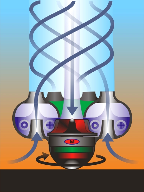
Thus the wheel creates 24 mini-tornados. The upper part of the
device looks like a copper basin (see Fig.4). Turning round the
internal surface of the upper part of the device, mini-tornados
move away to the internal cone of the device and forward the
outlet.
Fig.4
The approximate demonstration of the internal arrangement of
Schauberger's device is shown in Fig.5
Fig.5
The cross section of the device allows understanding of the
essence of tornado, which is observed from the vertical view.
The first section, which is placed a little lower than the
"copper basin", is the cross-section of the tornado. The rest of
two sections are placed closer to the outlet (only 9 balls are
represented in Fig.6 but the principle of operation is the
same).
Fig. 6
Thus, 24 (9) balls (mini-vortices) roll inside the wall of the
circle. The walls of each ball rotate in opposite directions
with respect to the walls of the neighbor balls. These balls
will be concerned as a dual medium: on the one hand it is a
ball, since it rolls as a part of a ball bearing and laws of
mechanics influenced on it, but at the same time it is air, for
which laws of hydrodynamic are valid. These balls at any
collision of their neighbors tend to collide to each other and
thus simultaneously move to the center of the device. At the
same time the opposite movement of walls of the neighbor balls
represent a rarified medium, by Bernoulli's law. Thus the balls
are "attracted" to each other. As a result, the whole mass of
the rotating air is constricted towards the center, and then
considerably accelerates (because the diameter of the device is
decreasing). Finally this mass flies out the nozale, which is
placed in the lower part of the device. The wheel with
"corkscrews" rotates, and constantly supplying these
minivortices-bearings, entrains air, which comes from inside...
Schauberger asserts that the process becomes to be
self-sustaining. Natural tornado can exist for a long period of
time and, obviously, the very existence of it is sustained only
by pressure difference between environment and the internal cone
of the tornado. The discharge zone is created in the very center
of the device. It means that ambient air must approach there,
after coming on the turbine blade and entraining in the rotation
with complicated trajectory (such a rotation can be called a
"self-eversible toroid").
It seems to me that these are the basic principles of operation
of the device. Indeed, such a process can be concerned as an
opposition to the ordinary explosion, since the matter
does not move from the center but on the contrary, tends to
constrict into the common point (to the top of the vortex).
Schauberger called this process as implosion.
The rotating mini-vortices, which composite a tornado, are
attracted to each other and tend to move to the basic center of
rotation.
Let us return to Schauberger. The witnesses of operation of
Schauberger's device asserted that only air and water were used
as a fuel. Possibly, they were wrong a little. Most likely there
were air and spirit, which looks like water. During the
operation the engine must consume ambient air and if to provide
it with some fuel and burn it, then it will forward the process
of the vortex creation. In the presence of the big amount of
oxygen, the flame of spirit is almost invisible. As a result,
there is a "flameless and smoke-free engine", as it was
presented in some publications.
In my conclusions I came to approximately the same design. Thus
I offer a device, which remotely resembles Shauberger's
"windmill". In general, operation of the device is based on the
same principles. The similar laws are valid for the whirlpool in
a bath and for the devices given below.
As distinct from Schauberger's device, there is no main cone,
along which the vortex constricts to the center and is ejected
through the nozzle. Another distinction consists in more simple
design of the wheel, which is used for creation of the vortex
(actually it is a usual centrifugal pump). The simplification of
Schauberger's design (Fig. 7) is caused by the fact that a
natural tornado does not need similar contrivances (though his
"corkscrew" wheel calls nothing but admiration, since by the
simplest and effective way it swirls air blasts at 2
perpendicular axes of rotation!). My aim is to swirl the air
blast into a small tornado as simply as possible and it is
desirable to use no mechanical components. This can be achieved,
if instead of turbine of centrifugal pump, we will use something
like MHD-engine (magnetohydrodynamic engine) for swirling (see
http://evg-ars.narod.ru). There is a design, which has no moving
components (except for the vortex). In the lower part of the
device (Fig. 8) there is a burning fuel (possibly, kerosene?).
Moreover for MHD-engine we should use electro-conductive
kerosene (possibly, salted) and natrium addition agent. Roughly
speaking, there is an attempt to reproduce the natural
phenomenon in a can. The essence of the process can be
understood from Fig.9.
Fig.9 "Tornado in a glass"
Fig10."Natural tornado"
The process, represented in Fig. 9 , was firstly noticed by
Einstein in an ordinary glass with tea and floating tea-leaves
(let us call it Einstein's glass). Examine closely the
central upward part, which is namely a "trunk of tornado". It
seems strange that Einstein did not made the same conclusions.
The processes, which take place in Einstein's glass, are
certainly the basis of the engine operation. Let us try to make
process stable. For that let us swirl water in a reservoir by
means of a disk, which is fixed on the axis of electric motor
engine (Fig.11). Having been swirled, water moves along the
complicated trajectory (fluid motion is described on
http://www.evert.de/, see
Fig.12)
Fig.11
Fig.12
These figures allow us make very interesting conclusions. Linear
speed of water motion is constant by all the way and it is
defined by linear speed of the disk edges. Fluid, which
is accelerated by the disk, spires down and forces itself to the
center. At that moment there is an increase of angular speed of
water rotation (if we rotate a weight hanging on a thread, which
is winded round the finger then we will see the analogous
increase of speed of rotation). Fluid with the increased angular
speed of rotation goes up and bears against the central part of
the disk. The most interesting is the fact that speed of
water rotation in the central part is higher than speed of disk
rotation! Water "pushes" the disk in direction of rotation.
The rotating stream supports itself! This is almost a
perpetual mobile. But force of friction is the usual obstacle.
This process occurs to be very stable and low-damping. The
conclusion is:
Vortex can be easily created at rotation of fluid or gas and if
the conditions of rotation at top and bottom of the device are
unequal, it is nearly a ready self-sustaining system.
Not much of energy is necessary to make the process continuous.
And what is more, the vortex absorbs energy from environment
in the form of heat!
Let us examine the simplified diagram of Schauberger's engine (
Fig.A ). The design can be presented as the following simple
diagram, which is nothing but the development of the idea of
Einstein's glass.
Fig.A Schauberger's Engine
At the top of the internal part of the device there is a
rotating disk (it is in red color). There is an upright plate
below. This design allows the unequal conditions of rotation for
lower and upper sheets of water (air?). On the left there is a
heat-exchanger (it will be described below). On top there is a
motor-generator, which at first serves as a starter of the
process, and after it reaches the tornado mode of operation it
serves as energy generator. A valve, which is fixed on the
heat-exchanger,serves as a breaker of the process. The arrow in
the left is an actuating fluid of the device. This actuating
fluid is heated by environment.
Centrifugal forces cause the increase of pressure at walls of
the vessel and rarefaction in the central part. Due to the high
angular speed of rotation of upper water (air) sheets, as
compared to the lower sheets, a meridional stream is created.
This stream goes down 'along walls of the vessel and goes up in
the central part (in nature it is nothing but "trunk of
tornado"). Moving along its complicated trajectory, fluid (gas),
falls sometimes into compression space, sometimes into vacuum
space.
Let us remember the fundamental physical law, vizBoyle's law If
we take a definite gas mass, then gas will be heated at forced
compression and cooled at rarefication. Thus, in the central
part of the device air-and-water compound comes to vacuum space,
which is caused by centrifugal forces. At that there is a
decrease of temperature and increase of volume of the final
gas mass. This increase of gas volume causes the increase of
kinetic motion of the stream, which comes upwards, along the
central axis of the device. This recharged stream with new
energy arrives to the turbine disk, forces it to rotate with
higher speed and to produce still more intensive vortex. This
vortex creates still higher rarefication etc. Cooled damp air is
thrown out by centrifugal force in the tube of the heat
exchanger. Ideally, temperature of the heat exchanger is about
absolute zero. The heat exchanger is placed in the environment,
which is "medium of energy excess", though from the ordinary
point of view it is normal. The heat exchanger is heated by it.
Heat energy penetrates into the device and as a result transfers
into energy of rotation of the "self-eversible toroid".
We can make an interesting conclusion that there is also the
oscillation process! And oscillations have a resonance, that
is the increase of amplitude at minimal energy supply' Thus we
will be able to stabilize the effect since there are evaluated
the dependences between amplitude of oscillation and all
influencing parameters. There is a temperature resonance!
In my opinion, Schauberger was a great person and his name is
undeservedly forgotten. I think he had nevertheless succeeded in
making a generator, which gets energy from "nothing",
more precisely, from environment. Even if it is made very
ineffectively, since this energy is free, it can remove all
against arguments.
I believe that there is a possibility to make such
engine-generator of amazing abilities, which can generate, or
more precisely, concentrate energy from environment energy.
Social and economic consequences of such invention are
undoubtedly boundless. That is both a solution of energetic
problems and change of the understanding of the notion
"transport".
From the foregoing, we can depict a certain design. Let's make
the following device as a hypothetical, "virtual" engine ( Fig.
B).
Fig.B Vortex engine-generator
This device can serve as:
1. Generator of energy, i.e. a concentrator of environment
energy.
2. Heat engine, which has abilities to cool and condition.
Besides, not necessarily to use water-air as actuating fluid,
since air and freon are also possible.
3. Gravitational mechanism. (This statement seems to be rather
bold, but let me explain it):
3.1. There is a well-known effect of weight loss of
fast-rotating masses. What does it depend on? Let us return to
Fig. 12. It is clear that at such a rotation of air there is a
possibility to run up J-»sq s to unconceivable speeds
(due to small air mass). The device is not threatened with
destroy, for example, as distinct from a metal flywheel. In
spite of complexity of the trajectory, each point of it moves at
a tangent to the Earth surface. It is quite possible to
reach 8 km/sec linear speed on this trajectory. If an artificial
satellite with 1m orbit can exist, then there is a question: "Is
levitation possible here?"
3.2. Some time ago an article on gravitational mechanisms
(mertioids) was published in "Technica Molodyozi" ("Technics for
Young People"). There was a description of about 10 types of
mechanism as well as the explanation why they could not fly.
However, in the end of the article it is stated that there is no
final verdict on the work of such devices, and the issue remains
open. Thus I offer #11. Let us concern the experiment I made,
i.e. the rotation of the usual flywheel, which was placed on the
axis of electromotor. I hold the motor with my hands. The
capacity of the motor was about 70 Wtt at 7000 r/min and U=24V.
The rotating flywheel (aluminum disk of 10cm diameter and about
200 gram weight) looks like an mertioid! It is enough to rotate
the device around your arm to feel incomprehensible propulsion,
which is definitely directed. This interesting effect is
obtained due to the simultaneous rotation around 2 axes (axis of
the motor and axis of the arm). The results of the experiment
caused the appearance of the idea, which has much in common with
Schauberger's device.
Thus we can formulate some general principles of operation of
the devices, which generate mechanical energy at "absorption" of
energy from environment.
1. There is a generation of the process, which is close to be
self-sustaining (We can find such examples in hydraulics. The
vortex of the type of Einstein's glass is very unstable and
rather inertial state. There are many examples in nature, such
as: swirl of water or air, natural tornado; in electrotechnics,
such as: electromotor and dynamo, which are connected on the
same axis, etc). For real self-support it is necessary to add
external energy in such a system. Sometimes energy, which ,
compensates losses by friction or resistance, can be enough.
2. There is amplification of the process right up to resonance,
which takes place in such a device (in vortex there is a process
of heating-cooling of air-water compound and in electrotechnics
there is the induction of electromagnetic fields).
3. The device is "reversed" with respect to the environment in
such a way, that some part of the device will have energy with
very decreased energy potential. This "reversing" will become an
absorber of environment energy. For example, in hydraulics the
central part of Shauberger's device is a space, which is close
to absolute zero by temperature and pressure. Therefore this
part of the device is placed in the usual environment of excess
energy potential. In electrotechnics it is more complicated,
since there is a superposition and resonance of fields.
4. There is a release of "absorbed" energy from the closed space
of the device in the form of mechanical or electric energy. This
energy is absorbed from the outside.
There are striking examples of such devices:
- Schauberger's Engine (see:
http://www.dromo.com/ fusionanomaly/viktorschauberger.html)
and Klem' s Engine, which is very similar by its principles
in hydraulics;
- Tesla's generator and Serl's generator in electrotechnics.
Thus we can conceive the interior of Schauberger's Repulsine.
Most likely, this device was similar to vortex engine-propulsion
unit-generator of energy ( Fig. C).
Fig.C Vortex engine-propulsion unit-generator of
energy
Vortex, which is created in the central part of the device,
absorbs heat from air, which traverses through turbine blades by
means of heat-exchanger. The heat-exchanger is actually a usual
centrifugal pump. Vortex absorbs that minimal part of heat,
which is necessary to keep rotation. The engine starts the
operation at turbine untwisting and at slight water injection,
which comes from below. Probably, after the mode of tornado is
reached, there is no need in water and only air serves as
actuating fluid. During operating of the engine, pressure is
decreased in the center and increased at the periphery of it.
Rank's effect works in full here. More precisely, its work is
even more pronounced than in "Rank's tubes" (since in Rank's
tubes swirled air is thrown outside instantly and rather
uneconormcally, and in the given case there is "accumulation" of
the effect at circular meridian rotation). The cooled from below
heat-exchanger-turbine is heated from above by compressed air.
The rejection of this cooled air causes usual reactive thrust.
If it actually works (I think that if Schauberger's engine
really existed, it had the similar design) then this design
could be considered as absolutely universal engine- propulsion
unit-generator of energy. It is super ecological and fuel-less,
since it has cool airflow as exhaust. Technological
effectiveness of the design is on the level of the beginning of
past century. Simplicity of the design can make us doubt its
capacity for work. But I believe there are no distinct
contradictions here. The commercial plant, designed for
generation of electric energy, could look in the following way (
Fig. D).
Fig.D Block of vortex electricity generating plant
The design is very simple. Why should the "vortex trunk" be
directed downwards? Let us turn the design upside down. Thus,
the generation of artificial vortex is greatly simplified. What
is necessary to create the vortex? The answer is as follows, we
need not much of environment heat, moisture and the initial
swirl of mass of damp air. A cup-shaped vessel is filled
with usual water. At the starting stage of operation,
motor-generator starts to swirl a water-air cone by means of
turbine with helical blades. When the device starts operating in
tornado regime, then heat is absorbed from the ambient air.
At that, motion of rarefied air accelerates along the center
of vortex and this airflow starts pressing upon turbine blades.
Motor-generator can be switched to the mode of
energy-generation. There is a minimal description of the device
operation, but really the processes are more complex (there is
advisedly left out the description of mini-tornado, which is
created at the appearance of the main tornado. The possible
electrostatic effects are not described also). Figure D is an
attempt to emphasize the main thing, i.e. the fact, that
process of vortex self-supporting is possible and in my
opinion, it is rather simple. I have no ideas about the height
of the obtained vortex (at least if the scales are kept it will
be much higher than in the Fig. D). But if the process of
natural vortices creation is ordinary (at that, sometimes there
are no obvious reasons for their appearance), then I offer to
consider the proposed device as a set of details, which provide
the artificial creation of the natural phenomenon.
There is another question on the size of the device. I do not
offer the giant size (50 meters in diameter Messiah mashine can
be concerned as such negative example). The description of
Schauberger's Home Machine Power seems to be more likely. Its
diameter is about 1 meter. Besides, my own design is a symbiosis
between thesetwo devices, however constructively it seems
simpler and probably better. Its minimal size is still defined
by laws of nature, since I have never seen natural air vortex,
the size of which was less than I meter (usual swirls on dusty
road are the simple example of such phenomenon). But at the same
time, if we imagine the maximal size of such a system, then our
imagination will easily picture a huge plant, which is placed on
the open air and which is able to generate a real tornado with
all its disruptive power. But this tornado is "tamed" and
therefore it always stays at one and the same place, i.e.
exactly over the energy plant. And what if we build a system of
large-scaled vortex energy plants, which are able to cool
environment? Then we can speak about the influence on climate'
It would be an important contribution to the global warming
control.
In my opinion, these devices can be widely produced as a
small-sized autonomous energy source (for example, for a
detached building). Do you remember how in their time personal
computers "thrown down" big electronic computers? It is
necessary to be closer to a consumer! For example:
???
Of course, everything looks rather fantastical, however I would
like to intensify the impression and to understand at last the
essence of Implosion and what Schauberger wanted to
offer.
Fig. 13 "Explosion" "Implosion"
Nowadays the whole man-caused civilization depends on
Explosion (in translation from Latin it means "explosion",
"exhaust"). Operation of any modern heat-engine (see the left
part of Fig. 13) is fuel combustion of a certain extension,
which causes raise of temperature and expansion of working body
due to this burning. The expanded working body pushes a piston
or turbine and then is thrown away to obtain reactive impulse.
Practically, operation of any engine is based on the process of
expansion, which is the result of fuel combustion, This causes
squandering of nonrenewable natural resources, viz: gas, oil,
coal, and uranium (the products of such a technology is a
separate great problem). However the expansion of the working
body can be obtained in result of absolutely different process!
Natural tornado can serve as an example.
Let me explain. Imagine that a working body rotates in some
vessel (the simplest case is the swirling of usual air (see the
right part of Fig. 13, which represents the miniature model of
natural tornado). Right away theaccelerating ascending
progressive motion will appear in the central part. There are
three reasons for that:
1. Due to the rarefication of the central part of the vortex
by centrifugal forces, there is a definite volume expansion of
final mass of gas and decrease of gas temperature. This mass
is "supported" by walls and bottom of the vessel. The only way
to expand is to move upwards.
2. In the central part of the vessel the rarefied part of gas
behaves according to Archimedean principle (more
lightweight body floats). It looks like a coverless balloon.
3. Swirling air obtains a considerable electric potential,
which is positive in the center and negative at the periphery.
In spite of its simplicity, this tornado model (as well as the
very tornado) is an excellent electrostatic generator (the
theory of appearance of such electric potential has the best
representation in materials on Searl's generator). In natural
tornado the millions Volt value is obtained that results in the
constant appearance of lightnings in "tornado eye" and in its
"trunk". Thus in the presence of such high voltage there
is air electrization in the body of tornado. And as is well
known, like charges repel each other! (Positively charged
air molecules, which are devoid of electrons, repel each other).
In such a way, due to electrostatic forces there is a rise of
gas pressure! This expansion causes the additional impulse for
the upward motion of air. Is there in physic a formulation of
such an effect, i.e. the expansion of gas volume at its
electrization? If there is no, then it seems to be a
discovery! Figure 14 is an attempt to prove, that tornado is
electrostatic machine, and at that it has the simplest design.
Fig. 14 Electrostatic model of tornado
The sectional view of tornado (see Fig. 14) represents an
attempt to synthesize the designs, which are offered by
different inventors (in such devices a simple cylinder serves as
rotor. This cylinder is made of dielectric and on each side of
it there is high voltage in several tens of KV). There is also
an attempt to answer the question: what are the means for
tornado swirling?
The researchers of natural tornados speak about the presence of
the system of mini-tornados at inner wallsof the mam tornado
(here I return to the balls-rolls,which were concerned above).
There is also high electric potential, which is generated on
this inner wall with respect to the center of swirling. In my
opinion, these balls-rolls are under high electric potential and
serve as rotors of the peculiar electric engine. That is an
immediate source of tornado swirling! There is a usual
process of electrization at friction of dielectrics (see the
animation on http://evg-ars narod). At some boundary voltage
there is "switching off" the forces of electrostatic attraction,
which compressed the balls. As a result of that, balls increase
in their diameter. Pressure release, which exists in the balls,
should cause their cooling. This process is constant along the
whole height of the tornado trunk. There is an interesting
effect to be noted, the higher speed of tornado, the thinner its
trunk. But these are electrostatic forces that can explain
everything ! The higher speed of swirling, the
more potential difference of the center and periphery is, the
more intensive attraction of the charged particles, and the
thinner trunk of tornado! Tornado has the ideal conditions
for electrization, since there are huge friction dielectric
surfaces (nobody knows why there is a transmission of electrons
at friction of wool on amber, but it does not mean we cannot use
that).
Let me summarize all aforesaid and offer my own design of the
vortex device. Most likely, during the XX century the inventors
of vortex devices have actually created really operational
devices, which used heat energy of environment (these are:
Schauberger's engine-generator, Klem's engine, Tesla's turbine,
Searl's generator, Roshchm-Godm's experiment (Editor's: See the
description of this experiment in the early issues of "NewEnergy
Technologies"), Potapov's generator, etc). All these devices
have much in common at their operation:
1. There is heat absorption at operation of the device,
and cooling of environment, which is a particular
"exhaust" (the reason is the conversion of environmental heat
energy into the swirling);
2. The presence of strong magnetic and especially electric
fields at operation of the device, caused by electric
forces, which are the reason of the process appearance;
3. Strange luminescence of the spaces, which are around the
devices and inside the vortices (the reason is air lonization at
multi-kilovolt voltages),
4. All devices have not less than 1 meter proportions
(since the operation of all these devices is based on the
presence of a vortex-tornado. Appearance of this tornado is
caused by physical properties of water and air, which are heat
capacity, heat conduction, breakdown voltage, sluggishness
etc).Let me summarize the principles of operation of all these
devices and offer my own design, which include the most useful
of them ( Fig.E).
Fig.E Arsentyev's Engine-tornado (sorry
- wrong polarizations!)
The device generates local natural tornado. There is an
attempt to elaborate the principles, which are in the basis of
the electrostatic model of tornado (see Fig. 14). In its
principle of operation the device has very much in common with
well known from school electrostatic generator (do you remember
2 rotating in opposite directions plexiglass disks covered with
foil and a lightning, appearing at breakdown between two metal
balls, which take the potential form these discs?). In our case
the whole device is rolled up in a cone. Rotating inner rotor,
which is made of maximum possible lightweight material (e.g.
thin-walled plastic), creates spiral and swirling on their axes
air bunches. These very air bunches are charge suppliers (they
are not presented at Fig.E).
The device operates in the following way: the plates are
positively charged on rotor and negatively on stator (metallized
black straps can be applied on the cone of rotor-stator by
galvanoplastics method). Engine-generator works as a motor until
the plates reach breakdown voltage. Then there appears a charge
between pairs of rotor-stator plates that causes appearance of
impulses, promoting acceleration of rotation. Inflow of "fresh"
air from below provides self-sustaining of rotation.
Motor-generator turns to the oscillating mode. Water, is pumped
from below and promotes intensification of air electrization
(there is an effect of intensive electrization at splashing of
water drops in air, e.g. waterfall streams). It is well known
that tornado is strongly "attracted" by ponds. That is the
principle of operation in general. The only energy sources are
water and a huge amount of air, transmitted through the
device. Lightweight thin-walled plastic with galvanoplastic
metallization can be used as a material for rotor-stator (the
usage of glued foil is also possible). The device must have not
less than 1 meter diameter, since it is very important for the
successful operation (there was a failure of Roshchm-Godin's
experiment with the device, which had 20 cm. diameter, whereas
the device with 1 meter diameter worked).
Do not forget to ground metal parts of motor-generator!
Here is the project of the generator. There are no elaborated
design drawings and everything should be tested. However, if it
is able to operate, then the similar commercial plant can be
easily produced, especially since the simpler device, the more
effective it is.
At this stage the author focused attention on generation of
energy, while creation of aircraft is the further
step in development of the project. Let us return to Schauberger's Repulsine, the electrostatic model of his device assumes the following approximate form ( Fig. F, G, H)
Fig.F,G,H Possible electrostatic model of Schauberger's
engine-generator by E. Arsentyev
Most likely, in Schauberger's engine "supply" air proceeds
from below and from above (i.e. there is a vortex chamber on
top of the device just as it is). Two mirror vortices have
common "tornado eye". During operation there is constant
electrization of the flow inside the device. Negatively
charged ring is created in the center of toroidal space
(according to the suggested electrostatic theory of tornado). In
principle, framework of the device can acquire positive
potential. However to make sure, it is better to ground the
framework. At electric breakdown of water-air compound there is
cooling and twisting of tornado cords inside the device. That is
a motive force of the device. Air ioni2ation is possible around
the framework (in the absence of grounding). At the first stage
it is offered to use classic Schauberger's turbine as turbine of
the device (corkscrews allow to obtain required twisting of
water and air flows inside the device). It is also possible to
use a usual doubled centrifugal turbine. The device can be made
of metal (as Shauberger's one) or of dielectric (for example,
plastic) that is more interesting from the modern point of view.
Diameter of the whole device is about 1 meter. Water-air cords,
which are generated by the corkscrews (or by blades in the
second case) have 3-5 cm diameter.
There are many publications on Koand effect, which appears
during the operation of Schauberger's engine. For some reason in
these works Koand effect is always described as an explanation
of wing lift. But Koand effect is a phenomenon of absolutely
another kind! It is the adherence of gas or fluid
flow to the surface along which they move! Obviously, the
problem is m the erroneous understanding of Shauberger's notes
about the presence of such effect during the operation of the
device. In my opinion, using Koand effect we can make a rotor
wheel, which has no blades or corkscrews. This rotor wheel can
have the form of doubled hyperbolic cone. At hyper-high
speeds of rotation of such a turbine, water-air compound
will be involved in tornado swirling exactly by means of
Koand effect, i.e. by means of adhesion of particles to the
surface of the rotating cone. (See cover page, Fig. H). By its
design this turbine is very simple, since only maximal lightness
and durability are demanded, Plastic seems to be the best
material, hence the design represents a rotor-thin-walled
plastic "whirligig". All electrostatic effects and other
principles of operation are valid here (See Fig.H).
Let us now move away from Schauberger's principles and formulate
the following problem- to achieve stability of the process by
modernization of the device, i.e. by removing of all
mechanically movable parts.
Can you imagine fireworks, which are the rotating wheels with
burning rockets on the rims? These rims gradually accelerate and
turn into the burning ring. It looks very effectively but
absolutely useless, at first sight. Speed of rotation is very
high but nevertheless it is definite. What is the limit for this
speed of rotation? Have you ever thought why usual electro-motor
is no table to rotate with the speed, •which is higher than some
maximal one, and no matter how long you will apply voltage to
the device? Everything is limited by moment of inertia, existing
for gyrating masses. This moment of inertia is denned by the
weight of rotating body and by weight distribution on the axis
of rotation. Therefore massive rotor of electric motor or of
rotating turbine can never be rotated up to super speeds.
Nowadays aircraft turbines have the highest speed of rotation
(about 150 thousand rot/mm). Why should we need to rotate a
heavy turbine or rotor? What if we will rotate air or, more
precisely, combustion products? Roughly speaking, I offer to
stop rotation of the firework wheel and force rotation of air or
combustion products along some inner rim. Therefore we will
obtain a burning ring, which will get required reactive force at
rejection of incandescent gases in proper direction. Let us
consider the problem from this point.
Operation of rocket engine is based on the expansion reaction,
which takes place in some closed space (at combustion of fuel +
oxidant in the chamber) and also the emission of combustion
products in the same direction. At that, a body moves in the
opposite direction.
Fig 15
Let us fill a cup with fuel and burn it (see Fig.15). Fuel
expands at combustion and as a result of natural convection the
combustion products go up. In the real rocket engine there is a
forced injection of fuel and oxidant into the cup that causes
more intensive motion of combustion products, than in our case.
Let us modernize the cup and make a hole in its center (see Fig.
16).
Fig. 16
Thus, portions of air can inflow from below and sustain
combustion. Expanding consumption products repel themselves from
inclined walls of the combustion chamber and therefore their
raise is more justified.
Fig. 17
Let us place several similar chambers one after another (Fig.
17). If we concern each chamber individually, then combustion
products at their expansion repel themselves from inclined walls
of the chamber and obtain some impulse. At that, the process
appears in the lower chamber and then becomes more intensive in
the second and all subsequent chambers. Thus combustion products
are gradually accelerated. There is a process of kinetic
energy storage. In order to make the process of storage to
be continuous, we should coil everything up.
Let us examine operation of the following device, which can be
made of a metal tin (see Fig. 18). The arrows symbolize burning
fuel, which obtains an impulse at the expansion. This diagram is
not connected with attraction as the presented above figures of
cups. It is caused by the fact that centrifugal forces come into
force, i.e. fuel is pressed to the rim and portions of air are
delivered by centrifugal force through the hole in the center of
the device (see the top view on Fig. 18).
Fig.18
In the center there can be placed a motor-generator to release
energy (see Schauberger's device). The presented design has 4
combustion chambers and most likely, the
vortex will be swirled of 4 rotating cylinders. Shauberger's
device has 24 cylinders at 1-meter diameter of the construction.
Such proportions can be justified in physical sense. In the same
way we can take the required number of chambers. Then the
vortex is contracted to point as in the aforesaid
description of balls-rolls.
The operation of the device is presented in Fig. 19 (view from
within). There is a toroid, which has self-support of
combustion reaction. The toroid draws air by means of
centrifugal force and throws up combustion products. Speed
of rotation of the toroid can be very high since its small mass.
At the same time, at superhigh speed of rotation of this tore,
some new and still unknown phenomena can become apparent. If
this engine really works, then there is no necessity of
production accuracy and of high technologies, which are required
for making of aircraft turbines and rocket engines. The only
essential requirement is heat resistance of the device. Such
an engine could be made at the appearance of ceramic stuff, i.e.
far earlier than modern era.
Fig 19
Now there is another "technological nonsense". I offer to make
the simplest air-reactive engine, which has no movable parts.
Certainly, many readers have used to observe benzine or another
inflammable substance burning in a metal bucket or barrel. From
time to time, tongues of flame create rising swirled vortex,
which disappears at once, since there are no special reasons for
its existence. What if we help the flame and spend for
rotation all energy, which is generated in result of expansion
of combustion products? Progressive motion will be the
consequence of this process.
Fig. 20
The device (see Fig. 20) represents a bucket with legs and a
hole in its lower part. To support the reaction, air inflows
from below. The plate-made, corona-like part of the device coils
up combustion products. Then under the influence of centrifugal
forces combustion products go up along walls of the bucket. New
portions of air aredrawn in the device from below and at once
react with each other (the more intensive combustion, the more
portions of air are drawn into swirling that in its turn
promotes combustion). The only aim is to forward all energy
output to swirling. This device is a miniature model of
typhoon-tornado-spout, i.e. a naive attempt to reproduce a
natural phenomenon in a simple leaky bucket. But there is still
undecided question: what is the reason for limitation of speed
of swirling and therefore speed of the flow, which goes from
below?
Fig.21
One more Schauberger's device is presented at Fig. 21. There are
some changes along the section A-A. Combustion products are
drawn to the center of swirling and then they are divided in two
flows: the first flow goes upward, creating the vortex, and the
second goes downward, making the motive force of the device.
Motor-generator is placed on the upper part of the device. It
operates as a starter of the process at first and as generator
of energy, after it reaches regime of tornado. Let me remind of
the fact that this engine uses energy, which is generated as a
result of fuel combustion (i.e. in any case, a kind of
liquid fuel is required). Schauberger asserts that it is
sufficient to use air and water as fuel. I am not sure it is a
realistic assertion, but later on I will try to offer my own
suggestion on the point, since from respect of energy consuming,
natural vortex has no need in something else
A-A section
Let me say several words about fuel for the device. It is
evident that at the initial stage of operation the device has
lack of air. Therefore, fuel should have oxidant in its compound
(something like napalm, which can burn by itself). But, quite
possible, I am wrong and usual aviation spirit is enough. Later
on I will try to develop this idea and modernize the design. The
main point will be the same, i.e. how to make engine, which has
no movable parts. There are so many new ideas on the variants of
engines that I am hardly able to describe them, not to mention
about making. If you will decide to make something similar,
please, write (mailto:evgars@evgars.com)
but let me get notice that everything is submitted in Internet
without diagrams and calculations.
To be continue... What do you think about? Best regurds for all from Evgeniy Aseev.
|
|
© 2015 Freely quoted with reference to the website of the author Свободноцитируемый, со ссылкой на веб-сайт автора
|